Design Bcd to Gray Code Converter Using 8 1 Multiplexer
Code Converters, Multiplexers, and Demultiplexers
Comparators
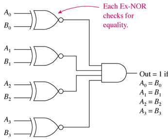
- A comparator will evaluate two binary strings and output a 1 if the two strings are exactly the same.
- The Exclusive-NOR (Equality gate) is used to perform the comparison.
- One Exclusive-NOR is used per pair of Binary bits and the outputs of all Exclusive-NORS are ANDed together.
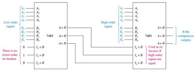
- The 7485 is a 4-bit magnitude comparator.
A magnitude comparator will determine if A = B, A > B or A < B.

- Expansion inputs are provided on the 7483 so that word sizes larger then 4-bits may be compared.
Decoding
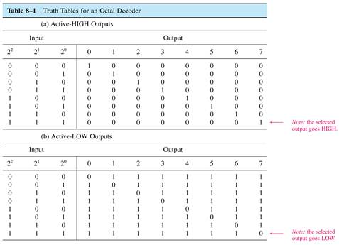
- A decoder circuit converts a binary code on the input to a single output representing the numeric value of the code.
- A binary-to-octal decoder converts 3 binary bits into a 1-of-8 output.
- Decoders can be designed with either active high outputs or active low outputs.
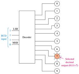
- A BCD decoder converts a 4-bit BCD code on the input to a 1-of-10 output.
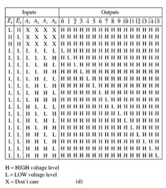
- A hexadecimal decoder converts a 4-bit binary code on the input to a 1-of-16 output.
- Any decoder that uses bubbles on the outputs has an active low output. No bubbles mean that the outputs are active high.
- Many decoder chips have a separate enable input to turn the chip on and off.
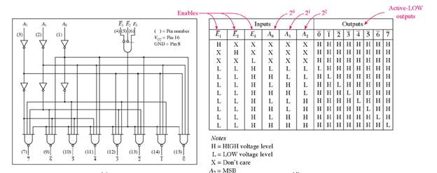
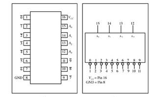
- The 74138 IC is an octal decoder with three enable inputs and active-low outputs.
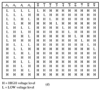
- The 7442 IC is a BCD decoder with active-low outputs.
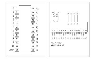
- The 74154 is a hex decoder with two active-low enable inputs and active-low outputs.
Encoding
- An encoder circuit will convert a single input out of several to a binary code on the output.
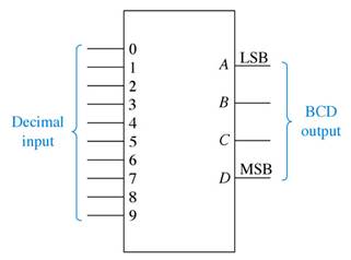
- A decimal-to-BCD encoder will convert one active input out of ten to a BCD code on the output.
- An octal-to-binary encoder will convert one-of-eight inputs to a 3-bit binary code on the output.
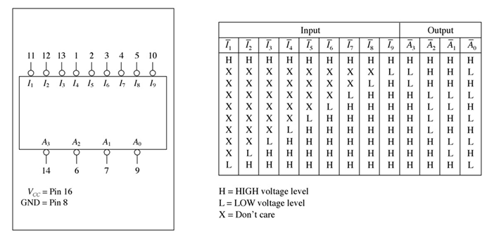
- A priority encoder such as the 74147 will output the proper code for the higher value of two or more active inputs and provide decimal-to-BCD encoding.
- The 74148 IC is an octal-to-binary priority encoder.

Code Converters
- A code converter circuit will convert coded information in one form to a different coding form.
- One example of code conversion is to convert BCD to straight binary.
- The weighting of BCD bits is not the same as straight binary. The weight of each bit within a BCD digit is 1, 2, 4, 8 respectively; but, each digit must be multiplied by its decimal positional value (1, 10, 100, 1000, etc.).
- The 74184 IC will convert 1 1/2 BCD digits to straight binary. (the LSB is the same in BCD and in binary).
- The 74158 IC is used to convert 6 binary bits into a BCD code (again the LSB is feed around the chip).
- Converters are also available that convert BCD input to a seven segment code output such as the 7447 IC.

Multiplexers
- The multiplexer (also known as a data selector) will select data from several transmission lines to be gated to the output transmission line.
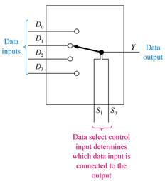
- The multiplexer will also have a number of control inputs that are used to select the appropriate data channel for input.
- The number of data inputs is equal to 2N where N is the number of control select leads.
- The 74151 is a eight-line multiplexer with three select lines.
- An additional input on the 74151 is an enable input which can be used to expand the size of the multiplexer.
- A multiplexer can also be used to implement a SOP Boolean Expression in combinational logic.
Demultiplexers
- A demultiplexer (data distributor) will select a specific output data transmission path from many for the input data to be sent to.
- The demultiplexer has several control select lines which are used to determine the selected output transmission path.
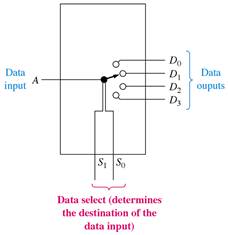
- The number of data outputs is equal to 2N where N is the number of control select leads.
- The 74139 is a 1-of-4 decoder that can also be used as a demultiplexer.
- To use the 74139 as a demultiplexer, connect the incoming data to the enable input and use the A0 and A1 inputs as the control select lines.
- The 74154 1-of-16 decoder can also be used as a 16 line demultiplexer.
- Several CMOS chips use a transmission gate as part of the multiplexer/demultiplexer. This means that the gate is bidirectional and can also handle AC signals as well as binary 1's and 0's.
System Design Applications
- Decoders are often used in microprocessor systems to decode the address information from the microprocessor in order to select the correct memory chip. A popular IC for this application is the 74138 or 74HCT138.
- Encoders are often used in microprocessor or in microcontroller applications to combine or group a large number of inputs down to a smaller binary count of the input activity. The 74148 is a popular IC encoder chip for these kinds of applications.
- Microprocessor based systems with serial input and output ports can use multiplexers and demultiplexers to route serial data to and from a number of different destinations. Multiplexers are used to combine several inputs into one and demultiplexers, or data distributors are used to send a single output to one of several destinations.
- An analog multiplexer can be used as a staircase generator which in turn can be used to provide a multiple input for an oscilloscope.
- A multiplexer/demultiplexer can be used to multiplex a 7-segment display system.
Additional Notes
Multiplexers and demultiplexers have many applications. The process of data selection and data routing have already been shown. Another important application is in parallel-to-serial conversion and in serial-to-parallel conversion. A multiplexer can be used to convert parallel data to serial data. the parallel data is applied to the data inputs and a binary count sequencer is connected to the control inputs. This means that the inputs will appear on the output one-at-a-time and in numerical sequence. Thus the parallel data will be applied to the output serially. The inverse (serial-to-parallel) can be accomplished with a demultiplexer.
Design Bcd to Gray Code Converter Using 8 1 Multiplexer
Source: https://grace.bluegrass.kctcs.edu/~kdunn0001/files/Code_Converters/Code_Converters_print.html
0 Response to "Design Bcd to Gray Code Converter Using 8 1 Multiplexer"
Post a Comment